
A warning light or low AdBlue consumption does not, by itself, prove that a DEF pump has failed. With first-generation Bosch Denoxtronic, liquid delivery, compressed-air assistance and electronic control all need to be considered.
This guide explains the operating principle, the main components and the application evidence available for Denoxtronic 1 / 1.1. It also outlines fault-investigation paths for workshops and parts specialists.
1. What do “Denoxtronic 1.0”, “1” and “1.1” mean?
Aftermarket terminology varies. “Denoxtronic 1.0” and “Denox 1” are common search terms, while Bosch's service literature explicitly uses Denoxtronic 1.1. This article focuses on that documented air-assisted architecture. Similar family names are not evidence that every hardware or software version is interchangeable. [1]
2. How the air-assisted system works
DEF travels from the tank through the supply module to the metering module. A spray attachment introduces the reductant upstream of the SCR catalyst with assistance from compressed air. Urea decomposition produces ammonia, which participates in the SCR reaction to reduce nitrogen oxides to nitrogen and water. [1]
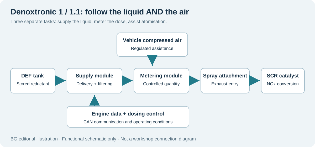
The first-generation design separates delivery, metering and exhaust entry. The supply module incorporates control electronics; the metering module controls quantity and adds compressed air; the dosing tube distributes the reductant into the exhaust. The compressed air is provided by the vehicle, rather than generated by the DEF pump. [3]
Engine and dosing control communicate over CAN. Engine speed, load and exhaust temperature influence dosing, so an engine running at idle is not automatically a valid condition for assessing normal DEF consumption. Confirm the dosing command and enabling conditions for the actual vehicle. [2]
3. Main components: identify the part, not just the system
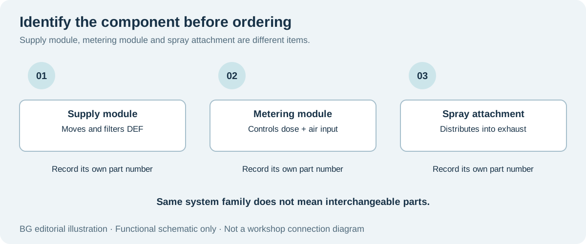
| Component | Role in the system |
|---|---|
| DEF tank and supply lines | Store and carry reductant. Sensor and heating arrangements depend on the vehicle. |
| Supply / delivery module | Deliver and filter liquid; house the relevant supply and control functions. |
| Metering / dosing module | Control reductant quantity and work with the air-assisted path. |
| Spray attachment / dosing tube | Introduce and distribute reductant into the exhaust. |
| Air regulation and control circuit | Provide the required compressed-air conditions. |
| Control electronics, wiring and sensors | Command actuators and provide operating and diagnostic information. |
| SCR catalyst | Carry out the catalytic reaction; it is part of the wider aftertreatment system. |
These component roles are based on Bosch's first-generation system description and service documentation. Do not automatically apply the physical layout of a later, compact dosing injector to a 1.1 installation. [1] [3]
4. Which commercial vehicles use this system?
Bosch's 1.1 service-tool application list includes DAF, MAN, IVECO and Scania, alongside Heuliez, Mitsubishi-Fuso, Temsa and UD Trucks. This confirms manufacturer-level coverage, not every model, engine or production year. [4]
| Application evidence | Catalogue family | Example OE reference |
|---|---|---|
| DAF, selected Euro V applications | Denoxtronic 1 | 1693191; 1791542 |
| MAN, selected Euro V applications | Denoxtronic 1 | 81.15403.6088; 81.15403.6098 |
| Scania, selected Euro V applications | Denoxtronic 1 | 1884220; 1884225 |
| IVECO, selected Euro IV / V applications | Denoxtronic 1 | 500059690; 504200399 |
The table is drawn from a remanufacturer's own catalogue and provides identification starting points—not an interchange list. A Scania aftermarket manufacturer also lists related supply-module references within the P-G-R-T range. Neither source establishes universal fitment across those vehicle families. [5] [6]
For exact selection, record the VIN, engine, emission level, full Bosch number and vehicle-manufacturer OE number. See BG's guide to identifying an aftertreatment part by OE number.
5. Typical fault symptoms and what to investigate
The following are diagnostic directions inferred from the system architecture and Bosch's test functions. They are not a failure-frequency ranking or a substitute for a vehicle-specific repair procedure.
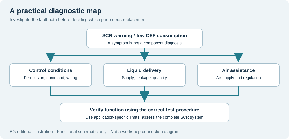
| Symptom | Investigation path |
|---|---|
| No dosing / unusually low DEF use | Verify dosing permission and command first; then assess liquid delivery, air assistance and metering response. |
| Abnormal supply pressure or delivery | Consider restrictions, leakage, pump delivery and feedback signals. Separate the supply side from the downstream metering side. |
| Air-circuit fault / poor atomisation | Check the vehicle air supply, line integrity and regulation or control functions. |
| White deposits around a connection | Investigate leakage or residual liquid. Removing visible deposits does not establish that the cause has been corrected. |
| Incorrect delivered quantity | Measure quantity under the prescribed test conditions; consider liquid supply, metering and air assistance together. |
| SCR efficiency / NOx-related warning | Assess dosing alongside exhaust temperature, sensor plausibility and catalyst condition. |
| Electrical or communication fault | Check power, ground, connectors, wiring and CAN using the applicable fault-code definition. |
Bosch's 1.1 equipment documentation covers pressure and air-circuit checks, valve operation, suction performance and measured return or dosing quantities. Fault codes help locate a fault path; functional testing helps distinguish hydraulic, pneumatic, electrical and mechanical causes. Use the limits for the correct component and procedure, rather than importing pressure values from later generations. [7]
Cleanliness is also essential. Bosch prohibits contaminating or casually diluting AdBlue. Cleaning residue from an external surface is not permission to add water to the vehicle's DEF. [1]
6. Finding relevant parts through BG
Start with BG's DEF / urea pump catalogue for supply assemblies, or the DEF pump repair-parts range when investigating repair components. These links are catalogue entry points; they do not establish Denoxtronic 1.1 compatibility for every item shown.
Send a clear label photograph, connector and port photographs, the complete OE number, and vehicle details through BG's parts enquiry page. Availability, component version and application need confirmation before ordering.
After repair, verify sealing and function using the relevant procedure rather than relying only on a cleared warning. Bosch lists dedicated 1.1 test adapters for repair-related checks. [8]
Sources and application notes
- Bosch Denoxtronic Set 1, 0 986 629 800 (2020), sections 2.4 and 3.1–3.2
- Bosch Denoxtronic 2.1 service instructions, section 1.5: first-generation comparison and CAN control
- Bosch Professional Automotive Information: Diesel Engine Management, 2014, p.207, DENOXTRONIC 1
- Bosch Denoxtronic service brochure: 1.1 manufacturer application list
- rema.germany AdBlue Supply Units: aftermarket family/OE reference table, p.2
- ORIONPART Scania catalogue, 2024, p.2: aftermarket P-G-R-T application range
- Bosch Denoxtronic 1.1 test-equipment instructions, 1 689 989 403 (2019), English pp.20–24
- Bosch tools for diagnosis and repair: Denoxtronic 1.1 test adapter
Bosch literature supports the system description. Sources 5 and 6 are aftermarket manufacturer catalogues, used only for application-reference examples. The fault table is an editorial synthesis, not a Bosch failure-rate report. Vehicle-manufacturer names and OE numbers identify applications; they do not imply endorsement of BG. Illustrations are original explanatory graphics and do not represent installation instructions.