
The BG 805001 Urea Pump Test Box brings pump test controls, electrical readings and diagnostic messages into one portable touchscreen platform. BG's demonstration shows pressure build-up and nozzle spray, illustrating its focus on practical AdBlue and DEF component assessment. BG is continuing to develop the functions and application coverage, with each pump configuration requiring the appropriate hardware, software and connection harness.
A urea pump can turn on without delivering the response a selective catalytic reduction (SCR) system needs. For a workshop, the useful questions are more specific: does the pump build pressure, does the dosing nozzle respond, and what do the electrical readings show during a test?
BG's demonstration materials present five areas of functionality: pressure build-up testing, injection testing, component testing, data display and fault detection. This article explains what the demonstration shows and how those observations can help workshop assessment.
BG 805001 at a glance
- Equipment
- portable urea pump test box for SCR workshop assessment.
- Observed in the videos
- touchscreen operation, Chinese/English switching, rising pressure readings and nozzle spray.
- Shown in the interface
- injection controls, component-test controls, electrical data, diagnostic messages and additional test-mode entries.
- Demonstrated pump configuration
- a screen labelled Bosch 2.2 BLDC 24 V; this does not establish compatibility with every pump in that family.
- Development status
- functions and application coverage are being developed progressively; confirm the available configuration with BG.
Observed in the videos = responses actually demonstrated. Shown in the interface = controls listed on screen; their completion depends on the validated version.
A dedicated platform for AdBlue and DEF component assessment
In an SCR system, the supply module delivers diesel exhaust fluid (DEF), commonly called AdBlue, to the dosing module. The dosing module then introduces the fluid into the exhaust stream as required. These related tasks need to be assessed separately: motor operation alone does not show whether the pump builds pressure, and a spray pattern alone does not show the complete electrical condition.
The BG platform is intended to help technicians examine compatible components in a controlled workshop setup. Bringing the controls and readings into one interface supports a more focused assessment before deciding which area needs further inspection. For background on the system itself, see how selective catalytic reduction works.
Portable case, integrated touchscreen and bilingual interface
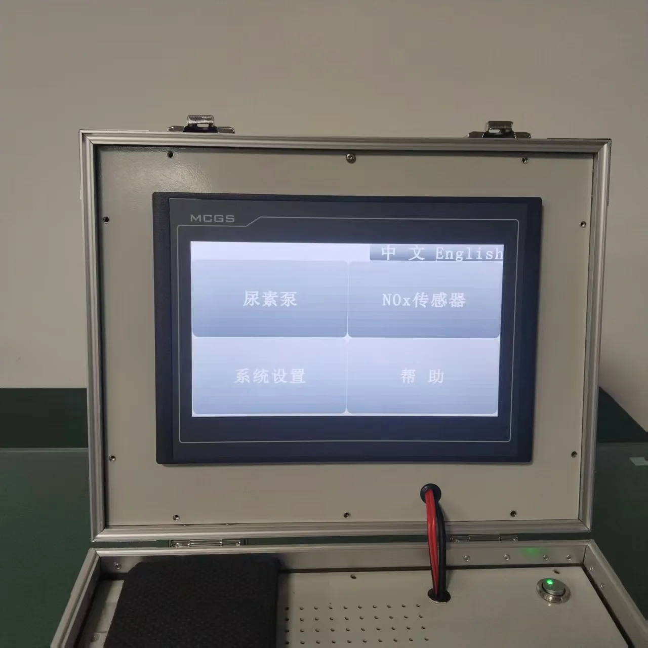
The demonstrated equipment combines its display and control hardware in a carrying case with a handle and latches. The operator can access the test interface from the box itself, with connection accessories prepared for the selected component.
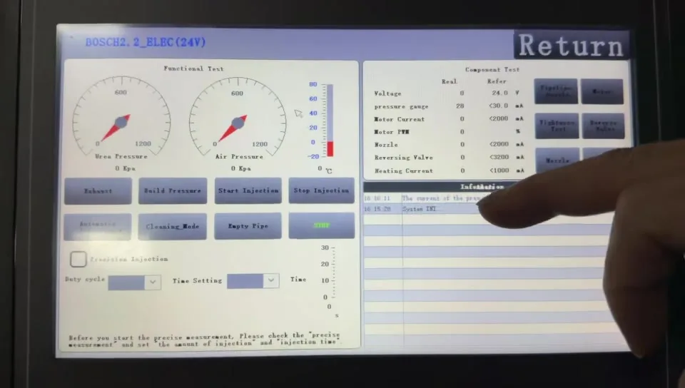
The walkthrough also shows switching between Chinese and English. In the pump test screen, the layout separates functional controls, component readings and an information log. This arrangement lets the operator follow the test action and its displayed response without moving between separate screens.
Product advantages for SCR workshops
The BG design brings several useful elements of component assessment together:
- 1
Controls and feedback in one view.
The operator can select a test action and follow the displayed pressure, electrical data and status messages on the same screen.
- 2
A view of both pump behaviour and individual components.
The interface combines functional controls with a component-test area, supporting investigation at different levels of the assembly. Availability of individual routines depends on the validated version.
- 3
Visible fluid-delivery evidence.
The workshop demonstration shows nozzle spray into a collection container, connecting the on-screen workflow to an observable response.
- 4
A portable, integrated format.
The case houses the display and control hardware together, making the platform practical to move between work areas.
- 5
Chinese and English interface options.
The demonstrated language switch supports users who need either language for everyday operation.
These advantages are about how the testing work is organised: the technician has a clearer connection between the command, the displayed feedback and the component's response. The demonstration does not quantify time savings or measurement accuracy.
Urea pump pressure testing: observe the build-up response
The Build Pressure control is one of the clearest actions shown in the longer demonstration. After activation, the displayed urea pressure rises and the information log reports the pressure-building sequence, including a success message.
This gives the technician a way to observe the relationship between a command and the pump's reported response. For troubleshooting, that is more informative than checking only whether a motor runs.
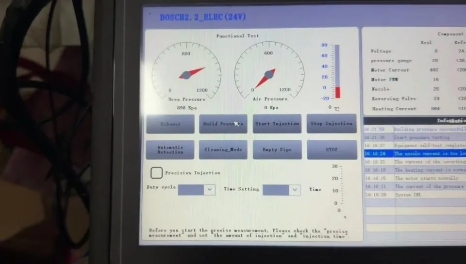
The correct target pressure and acceptance criteria depend on the pump and test procedure. A changing screen value demonstrates the displayed response; it does not, on its own, establish the tester's measurement accuracy or the condition of every part in the system.
DEF dosing and injection testing: observe nozzle delivery
The pump interface includes Start Injection and Stop Injection controls. The shorter workshop video also shows a connected dosing nozzle spraying into a collection container, providing a visible example of fluid delivery in the demonstrated setup.
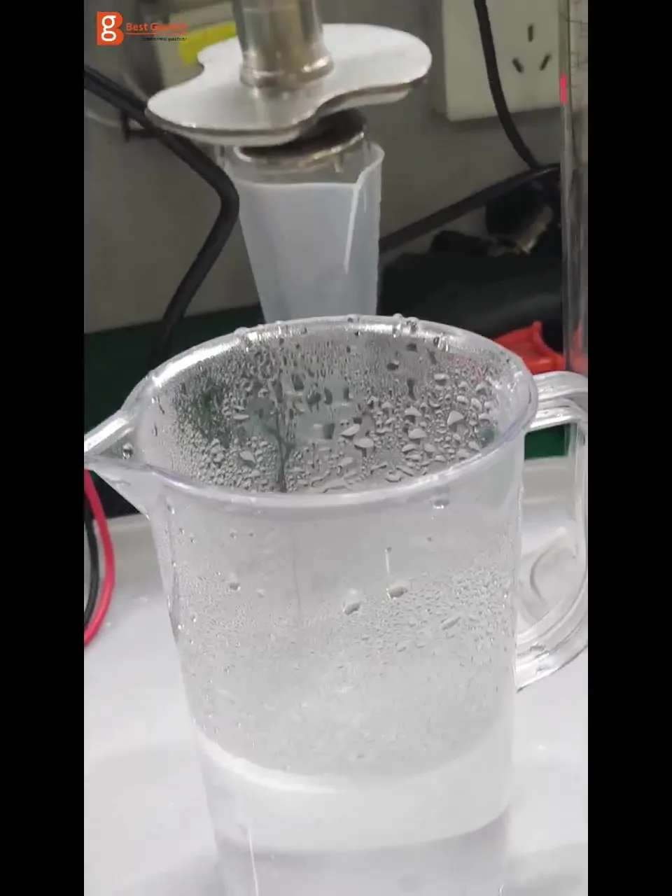
This is useful because actuator response and delivered quantity answer different questions. Visible spray shows that delivery is taking place under the demonstrated conditions. A quantitative dosing check additionally needs a defined test interval, suitable collection equipment and the relevant acceptance limits.
The interface also presents a Precision Injection selection, duty-cycle setting and time setting. These are controls shown in the walkthrough, rather than evidence of a certified dosing accuracy. Their operating range and application support should be confirmed for the supplied version.
Component testing and electrical data
The demonstrated screen includes a component-test area with motor, reversing-valve, heating and nozzle controls. Its data panel displays fields for voltage, a pressure-related signal, motor current, motor PWM, nozzle, reversing valve and heating current, alongside reference values.
For a technician, this layout can support a more specific investigation. A complete pump sequence examines overall behaviour; an individual component check focuses attention on a particular actuator or electrical response.
The panel also illustrates why voltage and wiring identification matter. The walkthrough uses a screen labelled for a Bosch 2.2 BLDC 24 V configuration. That demonstration should not be extended to every Bosch pump, every 24 V component or other pump families without the corresponding application validation.
Diagnostic messages help interpret the next step
The information log shows test status and diagnostic messages in the same view as the operating data. Messages visible in the walkthrough include equipment self-test completion and warnings concerning nozzle current, as well as pressure-test status.
A message such as low nozzle current gives the operator a reason to investigate the connection, wiring, selected configuration or component response. It should be interpreted with the test conditions and electrical readings, rather than used as a complete diagnosis on its own.
The interface also contains Automatic Detection, Cleaning Mode, Empty Pipe and stop controls. These demonstrate the intended operating structure. Completion and availability of each routine remain specific to the software and pump application as development progresses.
Urea pump compatibility and application-specific harnesses
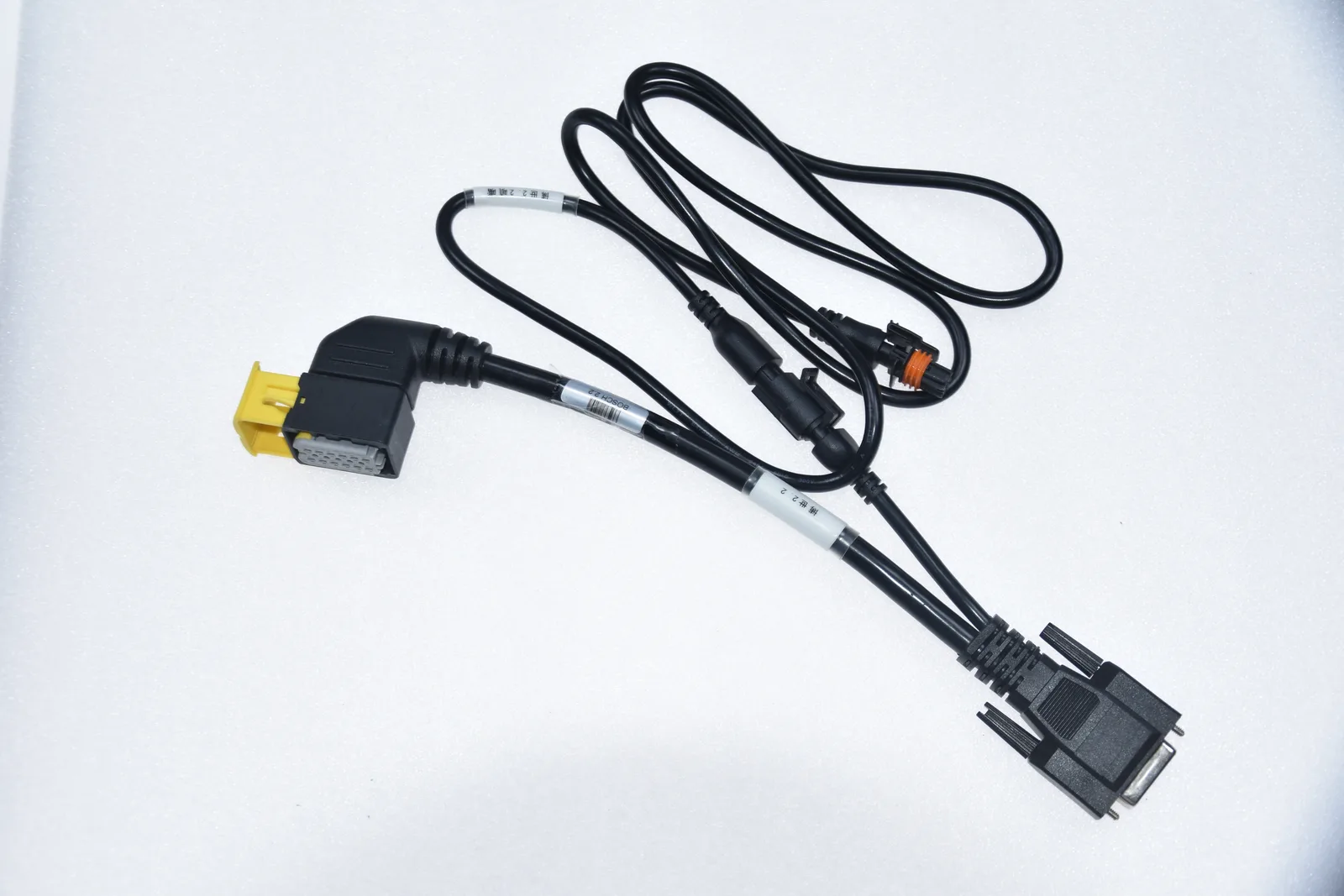
A test box, its software and its harness work as one system. Matching the pump requires its part number, operating voltage, connector details and pin assignment, as well as support for the relevant control routine.
The selection menu in the video contains multiple pump options. Those entries are useful for understanding the interface structure, but they should not be treated as a validated compatibility list. The same applies to the NOx sensor entry on the home screen: it identifies an area of the platform, while the supplied videos focus on the urea pump workflow.
How the platform can support workshop decisions
For diesel repair workshops and SCR component specialists, the intended benefit is a clearer link between the selected action, the displayed data and the component's observed response.
Pressure build-up can support investigation of delivery behaviour. Injection observation can help assess nozzle response. Component readings and diagnostic messages can guide further electrical checks. When the test conditions and acceptance criteria are defined, these observations can also provide a basis for comparison before and after repair.
Component testing remains one part of the diagnostic process. Vehicle wiring, control logic and operation under actual vehicle conditions may still need separate assessment. Related reading: P204F reductant system performance diagnostics and common SCR system faults.
BG's R&D approach: integrating hardware, software and application connections
The project materials show BG's development work across the physical enclosure, operator interface, electrical connections and pump-testing workflow. The case designs and project photographs document the equipment layout; the Version 1.0 videos show the interface in operation and the response of the connected test setup.
This matters because a useful SCR test platform needs more than a display or a selection menu. The control hardware must work with the software, and the connection harness must match the component's electrical requirements. BG's project brings those elements into one development programme.
The dedicated harness materials also show attention to application-specific connections. Pump voltage, pin assignment and control behaviour need to be considered together when extending the platform to another application. For workshops, this makes the confirmed pump-and-harness configuration an essential part of product selection.
The versioned demonstration and multiple equipment layouts document development through successive configurations. As functions and application coverage expand, the important next step is to validate each configuration and make its supported tests clear to the user.
BG's engineering direction is therefore concrete: combine component control, operating feedback and application-specific connections in a workshop-oriented platform, then develop and verify the function set progressively. Customers can discuss their actual pump references with BG to help define the required configuration and testing scope.
Discuss your pump testing requirements with BG
To evaluate the BG 805001 for a particular application, provide the pump part number, operating voltage, label photograph and connector photograph. Ask BG to confirm the available test functions, compatible harness, software version and any external equipment required for fluid collection or measurement.
Contact BG for the current application list, operating information and development status of the urea pump test box.
For technical discussions, share the checks your workshop needs to perform—pressure response, nozzle operation or a particular component assessment—alongside the pump identification. This gives BG a specific application requirement to evaluate.
Send an inquiry about the BG 805001Frequently asked questions
What is a urea pump test box used for?
A urea pump test box provides controls and data for assessing compatible SCR supply and dosing components in a workshop setup. Pressure response, injection behaviour and electrical readings help technicians identify the next area to inspect.
What does the BG 805001 demonstration show?
The BG videos show touchscreen operation, Chinese/English switching, pressure readings rising after a build-pressure command and a connected nozzle spraying into a collection container. The interface also displays component controls, electrical readings and diagnostic messages. The demonstration does not establish completion of every listed function.
Can the BG 805001 test every AdBlue or DEF pump?
Compatibility must be confirmed for the pump part number, voltage, connector, pin assignment, harness and software version. Multiple pump options appear in the selection menu, but a menu entry alone is not evidence of a validated application.
Does visible spray prove correct dosing quantity?
Visible spray demonstrates delivery under the observed test conditions. Verifying dosing quantity requires a defined test interval, suitable collection and measurement equipment, and acceptance criteria for the selected pump and nozzle.
Is NOx sensor testing demonstrated in these videos?
The home screen includes a NOx sensor entry, but the supplied videos focus on the urea pump workflow. Confirm current NOx sensor functions separately with BG.
This article describes the equipment and interface shown in BG's demonstration materials. Functions and application coverage are being developed progressively; final specifications, accessories and availability should be confirmed for the relevant version.